Prrrr...
prrr...prrr...(2800rpm)..prrr...prrr...prBang!...(900 rpm). Grab the stop
handle.
Crew,
all three rather sleepy, are suddenly with it.
“Whathappenedwhatwasthat???? Skipper,
now also wide awake, with the stop handle and about half a meter of cable in his
hand, swore in both available languages. “Hope
it was something in the prop”. Four
heads over the rail. Calm water. No sign of rope ends or other nasties. 200
meters from the berth. Up with a bit of sail. Slow drift into berth.
Tie up. Then the customary (Norwegian) anchor dram.
We
had just finished well in the Ballad class in the 65 nm. Færder Regatta, June
2001, starting from the inner Oslo harbour, then out the Oslo fjord to the
Hollender mark and half way back and were looking forward to some food and sleep,
not trauma.
Motor,
now just outside the extended guarantee, repaired by the VP agent who had
installed it in 1996. New head complete. One new piston and pin. All cylinders
honed. New rings. New big-end shells. (NOK 25 000)
The
Volvo Penta MD 2020 B is an 18 HP, 3 cylinder diesel, 0,68 L. swept volume. When
healthy it starts easily, runs very smoothly and quietly and is very economical,
about 1,1 litres per hour at 5 to 6 knots cruising speed. A suitable replacement
for MD 6 or MD 7.
In
2003, we heard of a sad tale from the Swedish Ballad Club of a very similar
incident, this time with the conclusion that the prime cause was corrosion from
sea water.
So,
we rushed to re-investigate the damaged bits, which had luckily not been binned.
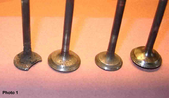
Photo
1 is of the valves of cylinders 2 and 3, after wire brush cleaning. No. 3
exhaust (aft) to the left. No doubt about it, all are corroded, with the
aft-most the worst. The piece missing from no. 3 exhaust is what caused the
damage to the head and piston.
So,
what was allowing sea water to get into the engine?
After
much one-sided correspondence with Volvo Penta Norway, (no use trying the local
company who had installed the engine and repaired it, as it had exasperatingly
gone broke in the interim), I received a copy of VP’s installation
recommendations, specifically relating to water circulation and exhaust
configuration.
My
installation did not comply.
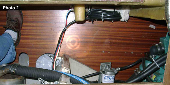
Photo
2 shows the installation, with the exhaust water-lock (under the trouser leg) to
the left and over a meter away from the engine, and higher than the exhaust
manifold outlet, just visible to the right. (Waterline is about 2 cm above the
line of screws visible in the plywood wall in the background). The hoses to and
from the anti-siphon valve, mounted correctly high enough up, partially hide the
exhaust hose. Rest of the exhaust, from the water-lock, is (also) 45 mm inside
diameter hose to a loop up under the afterdeck and out vertically downward just
above the waterline.
What
was probably happening was that much water was left in the long hammock of
exhaust hose after the engine was stopped. Subsequent motion under sail allowed
this water to slosh back and forth and run into particularly the aft cylinder.
Corrosion was inevitable.
Alarm
bells rang, and the head was removed for inspection.
(Three seasons and about 450 running hours since the repair).
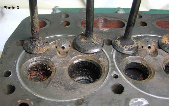
Photo
3 is of the no. 3 cylinder, with severe corrosion of the exhaust valve, (condition
as dismantled), and less to the others. Oh dear!
Almost another disaster. What to do?
Compared
to the original VP MD 7, a slower-running, two cylinder, uneven firing engine,
the new MD 2020, with its three, even-firing cylinders, blows much less exhaust
more evenly. Not so good at spitting water therefore. I also have a suspicion
that the seawater pump on the MD 2020, which according to the VP spares list, is
common with larger engines in the same series, may well pump more water than is
strictly necessary. (Experiments with a smaller cam in the pump will be carried
out later).
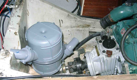
Photo
4 shows the new water-lock in a new position inside the engine cowl, in its
lowest possible position. Outlet as per original set-up. The water-lock
conflicts with, and prevents access to, the prop-shaft seal. (Old one in this
picture).
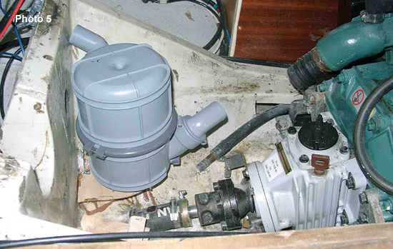
Photo
5 shows the new water-lock mounted in its final position, slightly to port, in a
cut-out and fibre-glassed recess in the engine cradle.
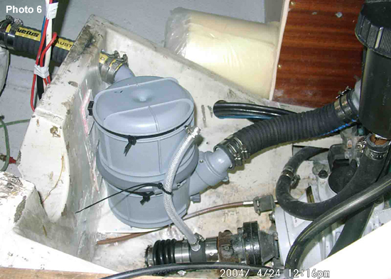
Photo
6 shows the water-lock in its final home, with new outlet through a new hole in
the cradle aft wall. Almost all the volume of the water-lock is now below the
engine exhaust outlet. A short outlet hose connects onto a stainless steel pipe
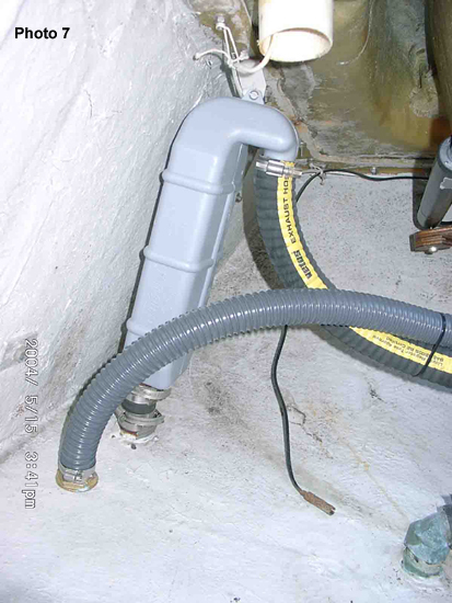
of 32 mm inside diameter. This pipe leads aft to a short hose connecting it with
the Vetus swan-neck, type LT 40, see photo 7, mounted close into the transom
and, with its outlet bend cut short, exhausting into the original exhaust skin
fitting.
The
gear control cable had to be re-routed to avoid the water-lock, but now has a
much better run and is much smoother in operation.
Also
visible in photo 6 is the new propshaft seal, from PSS, an axial seal, carbon
against polished stainless steel. The transparent hose is to bleed the air out
of the seal at launch time. Necessary.
The
corrugated hose in photo 7 is the bilgepump outlet. This is not a satisfactory
permanent solution as this type of hose, when bent sharply or trodden on (yes it
has happened!), splits open. Bad news, wet feet.
Everything
is now back and working, the boat is now afloat and short engine trials have
been carried out.
For water in
the exhaust, following normal shut down:
Detach the
exhaust hose at the engine exhaust manifold end, and see if any water runs out.
Arrange a
bypass in the seawater circulation which opens automatically at engine idle,
thereby reducing the amount of water pumped into the exhaust at idle, but
closing automatically on increased revs and therefore load.
Alternatively a bypass with a cock in it, to do the same, but then it
would have to be remembered to be operated!
The previous
engine also died through corrosion, through an exhaust port wall in that case.
Photos: